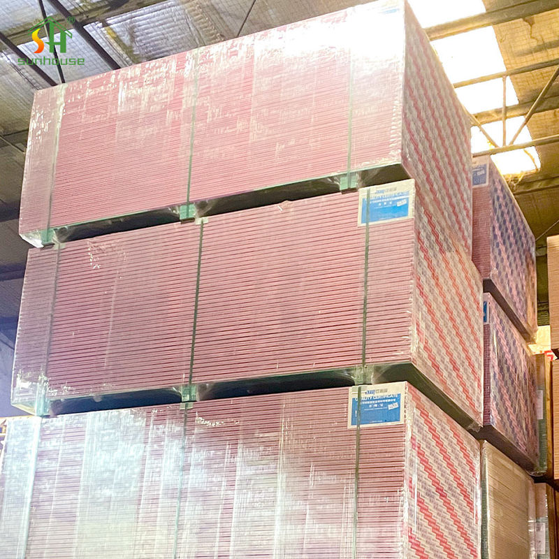
|
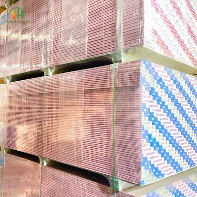
| Markenbezeichnung: | SUNHOUSE |
| MOQ: | 500 STÜCK |
| Lieferfähigkeit: | 3000000 Meter/misst pro Monat |
Die Dicke und Schichtmenge der Gipskartonplatten wirkt sich direkt auf das Systemgewicht, den Materialverbrauch, die Installationszeit und die Projektkosten aus. Allerdings bestimmen sie nicht unabhängig, ob eine Wand oder Decke eine Feuerwiderstandsdauer von 30, 60, 90 oder 120 Minuten erreicht. Für eine ordnungsgemäße Beschaffung müssen Käufer den genauen Plattentyp, die Dicke, die Anzahl der Schichten und die Installationsdetails mit einer geprüften oder aufgeführten Konstruktion abgleichen.
Bestätigen Sie die genaue metrische oder imperiale Dicke, die im genehmigten System angezeigt wird, anstatt nur den Preis pro Blatt auszuwählen.
Identifizieren Sie die erforderliche Basisschicht, Deckschicht und Gesamtzahl der Schichten auf jeder Seite des Rahmens.
Überprüfen Sie die Fugenstaffelung, die Brettausrichtung und die Umfangsbehandlung, da durchgehende Fugen zu schwachen Pfaden führen können.
Überprüfen Sie Bolzen, Isolierung, Schrauben, Abstände und Durchdringungen sowie die Plattenkonfiguration.
Eine dickere feuerbeständige Platte kann mehr Gipsmasse liefern und unter Hitzeeinwirkung länger schützend bleiben. Eine mehrschichtige Auskleidung kann auch zusätzlichen Schutz bieten, indem sie die Menge an Gips erhöht und direkte Wege durch Plattenfugen reduziert. Dennoch bezieht sich die endgültige Bewertung auf die gesamte geprüfte Konstruktion und nicht auf ein einzelnes Blatt.
Eine feuerbeständige Platte mit 15 mm, 15,9 mm oder 5/8 Zoll ist nicht automatisch eine 1-Stunden-Platte. Zwei Schichten sind nicht automatisch ein Zwei-Stunden-System. Die erforderliche Dauer muss durch eine vollständige Baugruppe unterstützt werden, die den Plattentyp, den Hersteller oder die zulässige Produktbezeichnung, den Rahmen, die Befestigungselemente, die Isolierung und die Installationsdetails angibt.
Die Produktstärken variieren je nach Land, Hersteller und Standard. Die folgende Tabelle dient lediglich der Beschaffungsübersicht. Die genehmigte Projektzusammenstellung bleibt die maßgebliche Vorgabe.
| Nenndicke | Gemeinsame Marktposition | Typische Überlegungen zur Beschaffung | Wichtige Einschränkung |
|---|---|---|---|
| 9,5 mm | Leichte Innenplatte oder Deckenplatte in ausgewählten Märkten. | Ein geringeres Gewicht der Einheit und eine einfachere Handhabung unterstützen möglicherweise nicht feuerbeständige oder speziell getestete Leichtbausysteme. | Es sollte nicht als allgemeiner Ersatz für dickere feuerbeständige Gipskartonplatten betrachtet werden. |
| 12mm | In einigen internationalen Märkten übliche Dicke für allgemeine Zwecke. | Bestätigen Sie, ob es sich bei dem gelieferten Produkt um ein Standardprodukt, feuerbeständig, feuchtigkeitsbeständig oder um eine Platte mit kombinierter Leistung handelt. | Eine allgemeine 12-mm-Platine sollte nicht durch eine getestete 12,5-mm- oder 15-mm-Systemkomponente ersetzt werden. |
| 12,5 mm | Weit verbreitete metrische Dicke für Wände und Decken. | Erhältlich in Standard-, Typ F-, Typ DF- und anderen marktspezifischen Feuerwiderstandsklassifizierungen. | Das Brandverhalten hängt von der Platinenklassifizierung und der vollständigen Systemkonfiguration ab. |
| 12,7 mm / 1/2 Zoll | Gebräuchliche nordamerikanische Nenndicke. | Kann als normales Board, proprietäres Typ X, Typ C oder andere Spezialprodukte erhältlich sein. | Eine normale 1/2-Zoll-Platine und eine proprietäre 1/2-Zoll-Typ-C-Platine sind nicht gleichwertig. |
| 15mm | Gemeinsame metrische Spezifikation für feuerbeständige Platten. | Wird häufig für feuerbeständige Wände, Decken, Schächte und gewerbliche Anwendungen in Betracht gezogen. | Gehen Sie ohne Systemgenehmigung nicht von einer Gleichwertigkeit mit 15,9 mm oder 5/8 Zoll Typ X aus. |
| 15,9 mm / 5/8 Zoll | Weithin anerkannte nordamerikanische Typ-X-Dicke. | Wird häufig als eine Komponente in denkmalgeschützten feuerbeständigen Wand-, Säulen-, Boden-Decken- und Dach-Decken-Baugruppen verwendet. | Der Vorstand stellt keine eigenständige einstündige Barriere außerhalb einer genehmigten Versammlung dar. |
| 18 mm und mehr | Spezialkarton, High-Density-Platte oder marktspezifisches System. | Kann eine verbesserte Schlag-, Akustik-, Struktur- oder Brandschutzleistung unterstützen, sofern speziell getestet. | Eine zusätzliche Dicke führt nicht automatisch zu einer höheren Brandklassifizierung oder ermöglicht weniger Schichten. |
Bei einem einschichtigen System wird eine Gipskartonschicht auf einer oder beiden Seiten des Rahmens verwendet. Es kann einen geringeren Materialverbrauch, eine schnellere Installation und eine geringere Wandstärke bieten, wenn es durch ein genehmigtes Design unterstützt wird.
Ein Doppelschichtsystem verwendet im Allgemeinen eine Basisschicht und eine Deckschicht. Es kann die Gipsmasse erhöhen, darunter liegende Fugen schützen und eine höhere Brand-, Schall- oder Stoßleistung unterstützen, wenn es in ein getestetes Design einbezogen wird.
Eine in einer 30-Minuten-Baugruppe verwendete Ebene plus eine weitere ähnliche Ebene erstellt nicht automatisch eine genehmigte 60-Minuten-Baugruppe. Die Leistung mehrerer Schichten hängt von der gesamten Konstruktion, der Fehlerfolge, dem Rahmenverhalten, der Verbindungsanordnung, dem Befestigungssystem und den Prüfbedingungen ab.
In einem mehrschichtigen Brandschutzsystem hat jede Schicht eine bestimmte Position und Befestigungsanforderung. Die Basisschicht wird am nächsten zum Rahmen angebracht, während die Deckschicht die endgültige freiliegende Oberfläche bildet. Diese Schichten sollten nicht neu angeordnet, weggelassen oder ersetzt werden, ohne das genehmigte Design zu überprüfen.
Diese Abbildung erläutert nur die allgemeine Schichtenfolge. Die tatsächliche Plattendicke, Anzahl der Lagen, Rahmen, Isolierung und Befestigungsdetails müssen dem geprüften oder aufgeführten System entsprechen.
| Ebenenposition | Hauptfunktion | Zu bestätigende Beschaffungsinformationen |
|---|---|---|
| Basisschicht | Stellt die erste Gipsmembran über dem Rahmen bereit und unterstützt die Deckschichtkonstruktion. | Plattentyp, Dicke, Ausrichtung, Befestigungstyp, Befestigungslänge, Schraubenabstand und Behandlung der Tragschichtverbindungen. |
| Gesichtsschicht | Fügt Schutzmasse hinzu, deckt die Fugen der Tragschicht ab und bildet die endgültige Oberfläche. | Plattentyp, Dicke, Fugenversatz, längere Befestigungselemente, Endbearbeitungsmethode und Umfangsbehandlung. |
| Gegenüberliegende Wandfläche | Vervollständigt die Trennwand und kann unerlässlich sein, wenn Feuereinwirkung aus beiden Richtungen möglich ist. | Überprüfen Sie, ob die Konstruktion symmetrisch ist oder auf jeder Seite unterschiedliche Brettschichten verwendet. |
| Schacht- oder Hohlraumauskleidung | Ist Teil eines proprietären Schachtwand- oder Hohlraumsystems. | Genaue Linerstärke, Kantenprofil, Rahmensystem und aufgeführte Produktbezeichnung. |
| Deckenmembran | Schützt Balken, Bodenkonstruktionen, Dachkonstruktionen oder Leitungen über der Decke. | Anzahl der Schichten, Plattenausrichtung, Aufhängungssystem, elastische Kanäle, Befestigungselemente und Umfangsdetails. |
Plattenfugen sind potenzielle Übertragungswege für Hitze, Flammen und Rauch. Bei mehrschichtigen Systemen sind die Fugen üblicherweise versetzt, sodass eine Fuge der Deckschicht nicht direkt mit der Fuge der Basisschicht übereinstimmt. Der genaue Versatz und das Installationsmuster müssen der genehmigten Montage entsprechen.
Der Abstand zwischen Tragschicht- und Deckschichtfugen, die Richtung der Plattenverlegung und die Behandlung von horizontalen und vertikalen Fugen variieren je nach System. Installateure sollten sich an der getesteten Zeichnung orientieren, anstatt einen Versatz nur aufgrund der Bequemlichkeit des Standorts auszuwählen.
Normale Board-, Typ-X-, proprietäre Typ-C-, Typ-F- und Typ-DF-Produkte sollten nicht als austauschbar behandelt werden.
Das System erfordert möglicherweise eine, zwei oder mehr Schichten auf jeder Seite mit unterschiedlichen Anordnungen um Schächte, Säulen oder Decken.
Stahlpfosten, Holzpfosten, Kanäle, Balken und proprietäre Rahmensysteme reagieren unterschiedlich auf die Brandeinwirkung.
Einrahmungstiefe, Spurweite, Achsabstand und maximale Wandhöhe sind Bestandteil des geprüften Systems.
Schraubentyp, Länge und Abstand variieren je nach Tragschicht, Deckschicht, Holzrahmen und Stahlrahmen.
Je nach Montage kann eine Mineralwolle- oder Glasfaserdämmung zwingend, optional oder eingeschränkt sein.
Klebeband, Fugenmasse, Umfangsdichtstoffe und die Behandlung der Befestigungsköpfe müssen den Systemanforderungen entsprechen.
Die horizontale oder vertikale Ausrichtung der Platten kann sich auf die Fugenanordnung, die Rahmenunterstützung und die zulässigen Installationsdetails auswirken.
Mit zunehmender Schichtanzahl wird die Auswahl der Verbindungselemente immer wichtiger. Schrauben der Deckschicht müssen durch die Außenplatte gehen und den erforderlichen Halt mit dem Rahmen oder dem zugelassenen Grundmaterial gewährleisten. Bei der Auswahl der Schrauben sollte daher der komplette Lagenaufbau und nicht nur eine Plattendicke berücksichtigt werden.
Zu viele, falsch positionierte oder zu stark angezogene Schrauben können die Plattenkanten und das Deckpapier beschädigen. Der richtige Ansatz besteht darin, den getesteten oder aufgeführten Schraubentyp, die Länge und den Abstand zu befolgen, anstatt ohne technische Begründung Befestigungselemente hinzuzufügen.
| Bauelement | Konfigurationsfokus | Wichtige Beschaffungsfragen |
|---|---|---|
| Trennwand | Plattenlagen je Seite, Ständertiefe, Ständerabstand, Dämmung und maximale Wandhöhe. | Ist das System symmetrisch und kann es von beiden Seiten zu einer Brandeinwirkung kommen? |
| Korridorwand | Feuerbeständigkeit, Stoßbelastung, akustische Privatsphäre und Servicedurchdringungen. | Ist eine widerstandsfähige oder feuchtigkeitsbeständige Deckschicht erforderlich? |
| Schachtwand | Schachtauskleidung, CH- oder proprietäre Bolzen, Deckschichten und Einbau von einer Seite. | Enthält das Angebot die genaue Schachtauskleidung und das Rahmensystem? |
| Boden-Decken-System | Deckenmembranschichten, Balken, Kanäle, Isolierung, Unterboden und Fertigböden. | Ist die Diele direkt am Rahmen befestigt oder durch elastische oder tragende Kanäle? |
| Dach-Decken-System | Deckenplatte, Aufhängungsmethode, Dachkonstruktion, Isolierung und Hohlraumgestaltung. | Erfordert die getestete Konstruktion eine Typ-X- oder eine proprietäre Typ-C-Platine? |
| Struktursäule | Anzahl der Gehäuseebenen, Eckbehandlung, Befestigungs- und Säulenabmessungen. | Ist das genaue Platinenprodukt und die Gehäusegeometrie im genehmigten Design aufgeführt? |
| Servicegehäuse | Plattenkontinuität um Kanäle, Rohre, Kabel und Zugangsöffnungen herum. | Sind kompatible Brandschutz- und Zugangsklappensysteme enthalten? |
Die folgenden Beispiele erläutern die Kauflogik, anstatt eine bestimmte Brandschutzklasse vorzuschreiben. Die endgültigen Systeme müssen aus der genehmigten Projektdokumentation ausgewählt werden.
Eine dünnere oder einschichtige Platinenoption mag günstiger erscheinen, die Gesamtinstallationskosten hängen jedoch von weit mehr als nur dem Plattenpreis ab. Käufer sollten das komplette Wand- oder Deckensystem vergleichen.
Berücksichtigen Sie Brettschichten, Bolzen, Schienen, Isolierung, Schrauben, Klebeband, Fugenmasse, Dichtstoffe, Zierleisten, Paletten und erwarteten Materialabfall.
Berücksichtigen Sie Entladen, Heben der Bretter, Schneiden, Fixieren, Fugenbehandlung, Trocknungszeit, Schleifen, Zugangsausrüstung und Qualitätsprüfung.
Berücksichtigen Sie die Kosten für abgelehnte Anträge, Neukonstruktionen, Ersatzmaterial, Verzögerungen vor Ort und Nacharbeiten, die durch eine nicht genehmigte Dicken- oder Schichtänderung verursacht wurden.
| Kostenartikel | Einschichtiger Effekt | Doppelschichteffekt |
|---|---|---|
| Board-Menge | Geringere Menge pro Wandfläche. | Ungefähr das Doppelte der Verkleidungsfläche pro Wandfläche vor Abzug der Abfallmenge. |
| Verwendung von Befestigungselementen | Ein primärer Reparaturvorgang. | Getrennte Befestigungsanforderungen für Grund- und Deckschichten. |
| Installationszeit | Im Allgemeinen schneller, wenn das zugelassene System eine Schicht zulässt. | Zusätzliche Hebe-, Positionierungs-, Befestigungs- und Inspektionszeit. |
| Gelenkbehandlung | Die letzten freiliegenden Fugen müssen nachbearbeitet werden. | Die Behandlung der Basisschicht hängt von der Baugruppe ab; Deckschichtfugen müssen nachbearbeitet werden. |
| Transportgewicht | Geringere Gesamttonnage der Bretter. | Höheres Containergewicht und mögliche Beladungseinschränkungen. |
| Schadenstoleranz | Der Schaden betrifft die einzige Plattenschicht. | Äußere und innere Schichten sorgen bei korrekter Installation für eine robustere Auskleidung. |
| Systemgenehmigung | Muss zu einer zugelassenen einschichtigen Konstruktion passen. | Muss exakt zum Mehrschichtaufbau und zur Fugenanordnung passen. |
Fügen Sie eine angemessene Projektabfallmenge hinzu, die auf der Plattengröße, der Wandgeometrie, den Öffnungen, den Schnittanforderungen, den Handhabungsbedingungen und den erwarteten Schäden basiert. Bei unterschiedlicher Anzahl oder Art der Plattenlagen sind beide Wandflächen separat zu berechnen.
Berechnen Sie für eine Trennwand mit zwei Plattenschichten auf jeder Seite insgesamt vier Verkleidungsschichten über die Wandfläche. Der Abzug von Öffnungen sollte sorgfältig überlegt werden, da in Tür- und Fensterbereichen möglicherweise zusätzlicher Schnittabfall, Übergänge, Kopfleisten und Verstärkungsdetails entstehen.
Die gelieferte Platte entspricht möglicherweise nicht mehr dem zugelassenen Brandschutzsystem.
Die Brand-, Akustik- und Strukturleistung kann beeinträchtigt sein.
Eine gerundete metrische Dicke kann fälschlicherweise als imperiales Äquivalent behandelt werden.
Für die Montage ist möglicherweise in jeder Schicht eine feuerfeste Platte erforderlich.
Die proprietäre Typ-C-Leistung kann für das aufgeführte System von entscheidender Bedeutung sein.
Ausgerichtete Verbindungen können einen direkten, schwachen Pfad durch die mehrschichtige Auskleidung erzeugen.
Die Schrauben der Deckschicht erreichen möglicherweise nicht den erforderlichen Rahmeneingriff.
Die Wand kann außerhalb der strukturellen und brandschutztechnischen Grenzen liegen.
Das Hinzufügen oder Ändern der Isolierung ist nicht automatisch in jeder Baugruppe zulässig.
Ungeschützte Durchdringungen können die Kontinuität des Brandschutzes gefährden.
Mehrschichtige Systeme können sich auf Handhabung, Containernutzlast und Rahmendesign auswirken.
Durch das Hinzufügen ungetesteter Schichten wird nicht automatisch ein anerkanntes System erstellt.
Nein. Eine größere Dicke kann zu mehr Gipsmasse führen, die endgültige Brandschutzklasse hängt jedoch von der vollständig getesteten Baugruppe ab. Eine dickere, nicht zugelassene Platte sollte das angegebene Produkt nicht automatisch ersetzen.
Nein. Feuerwiderstandszeiten können auf diese Weise nicht addiert werden. Der zweischalige Aufbau muss durch ein geprüftes bzw. denkmalgeschütztes Wandsystem gestützt werden.
Nicht automatisch. Zwei Schichten sorgen im Vergleich zu einer dicken Platte für eine unterschiedliche Fugenabdeckung, ein anderes Befestigungsverhalten und eine andere Fehlerfolge. Für jeden Ersatz ist eine genehmigte technische Dokumentation erforderlich.
Nur wenn das zugelassene System das metrische Produkt und seine genaue Klassifizierung zulässt. Die Nennmaße liegen nahe beieinander, sind jedoch nicht automatisch technisch gleichwertig.
Befolgen Sie die Montagespezifikation. Einige Systeme erfordern feuerbeständige Platten in jeder Schicht, während andere möglicherweise unterschiedliche Produkte für bestimmte Positionen vorschreiben.
Die Anforderungen variieren zwischen den Systemen. Bei einigen Baugruppen ist die Behandlung der Basisschichtverbindungen vorgeschrieben, während andere auf der abdeckenden Deckschicht basieren. Die geprüfte Einbauanleitung soll die Entscheidung leiten.
Nur wenn das zugelassene System eine Gips-an-Gips-Befestigung mit den angegebenen Befestigungsmitteln oder Klebstoffen zulässt. Bei vielen Systemen sind Befestigungselemente für die Deckschicht erforderlich, um in den Rahmen einzugreifen.
Viele mehrschichtige Systeme erfordern versetzte Verbindungen. Die genaue Anordnung sollte sich an der genehmigten Zeichnung orientieren und nicht an einer allgemeinen Standortregel.
Zusätzliche Schichten mögen konservativ erscheinen, sie können jedoch das Systemgewicht, den Eingriff der Befestigungselemente, die Rahmenlasten und Konstruktionsdetails verändern. Holen Sie die technische Genehmigung ein, bevor Sie Änderungen an der geprüften Anlage vornehmen.
Bestätigen Sie die Plattenklassifizierung, Dicke, Abmessungen, Schichtanzahl, Schichtposition, Baugruppennummer, Rahmen, Befestigungselemente, Isolierung, Verbindungsanordnung, Verpackung und Produktidentifikation.
Geben Sie die erforderliche Branddauer, den Zielstandard, die Montagenummer, die Wand- oder Deckenstruktur, den Plattentyp, die Dicke, die Anzahl der Schichten und die Projektmenge an. Die Konfiguration kann dann auf technische Konformität, Materialverbrauch, Containerbeladung und Gesamtprojektkosten überprüft werden.

 english
 français
 Deutsch
 Italiano
 Русский
 Español
 português
 Nederlandse
 ελληνικά
 日本語
日本語
 한국
한국
 العربية
 हिन्दी
 Türkçe
 indonesia
 tiếng Việt
 ไทย
ไทย
 বাংলা
বাংলা
 فارسی
فارسی
 polski